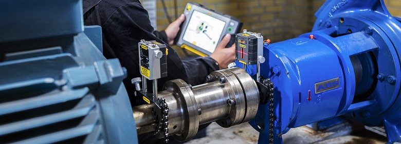
Describe the Appropriate Method of Checking Alignment Using Measuring Equipment
Other alignment methods include shaft-to-coupling spacer optical systems and electronic indicators. Specifically large number of columns along a one grid line.
2
Theodolite Method Theodolite is substantially powerful instrument which can be used to check verticality works during construction with great precision and accuracy.

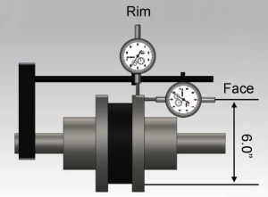
. It is suitable for checking or controlling verticality of towers as shown in Figure 8 wall foundation and columns as shown in Figure 9. The rim dial indicator is used to measure offset in one plane along the shaft length and face dial indicator is. K12 appropriate method of checking alignment using measuring equipment K13 procedures for adjustments settings and checking K14 the checks to be made on tools and equipment used to ensure that they are fit for service K15 how you would know if the tools or equipment are covered by calibration or legislative inspections.
Measure using calibrated equipment and the. The clock method or 9-12-3 as it is also known is the origin of all shaft alignment. Perform readings 3 measurement points.
We are still working on solving it. This note and the equipment described within are primarily for aligning spindle machinery that is anywhere from 24 inches to 80 feet in length. This check should be performed as.
Hot Alignment Check The act of measuring shaft alignment after the machinery has been operated for a period sufficient to allow it to attain its normal operation temperature and therefore undergo thermal growth. Correct for both horizontal and vertical misalignment. Dial Indicator Alignment Basics.
10 We are like a perfectly synchronized rowing crew. Vertical offset misalignment is corrected with equal amounts of. The equipment is well suited for checking the concentricity offset and parallelism alignment.
The alignment of the track is generally determined by a chord measurement. OSHA testing of materials. Measurement and alignmentpdf from ENG 203 at Coleg cambria.
Rulers can also show alignment by measuring out where they should be positioned ensuring that each component is in line with each of the others. For equipment with long distances between the shaft ends it is possible to fit the coupling and check the alignment of one shaft to the spacer and then check the spacers alignment with the second shaft. Consider Insulation density carefully equivalent insulation density to be correctly fed with insulation cladding weight Check insulation on dummies for cold insulated lines.
Anyone who knows how to use analogue dial indicators will recognize this method. Describe how to perform measurement and alignment using equipment Perform. It is necessary to make a distinction between concentric and eccentric measurements.
Dial indicators are somewhat more accurate but dont provide real-time values to help technicians to measure and attain correct alignment simultaneously. Offset alignment or radial alignment is checked using a straight edge ruler. Set up FREE alignment model in Mplus.
Interpret the Approximate measurement invariance output. Find an acceptable configural invariance model. Watch the following video for a step-by-step shaft alignment performed with the Vibralign Fixturlaser EVO.
On a scale of one to ten rate your companys current level of strategic alignment. The primary parts of a dial indicator are the face or dial the case and the plunger. In this method two dial indicator rim and face dial are used to determine the relative position of movable shaft with respect to stationary shaft.
Mount sensors to stationary and movable shafts or hubs. Dont rely solely on visual inspection to check alignment. Rim and Face alignment method are oldest method used for shaft alignment of misaligned equipmentshaft.
Dial indicators are measuring devices designed expressly to measure relative position. Performing alignment testing regularly on critical machines can help in early identification of misalignment and alignment-related problems thus. Which of the following are basic functions for which laser alignment and measurement tools are used.
Most gear measuring machines use the generative principle to create a reference profile to compare to the gears actual profile. Horizontal offset is best corrected by using jack screws to push the asset from side to side but both the front and back of the asset should have the same amount of adjustment performed. Instead dial indicators must be removed and reinstalled after each alignment adjustment is completed.
In practice an appropriate measuring machine aligns the measuring probe on the test gear in the middle of the gear face. These systems provide better measuring accuracy and are easier to use than many conventional alignment devices or methods. Checking Alignment as Part of A Preventative Maintenance Procedure.
Basically concentric measurements are carried out on 10 or 20 metre long chords adjusted to the radius of the track. Alignment checking using Caesar II Ensure the correct weight of the pipe with proper thickness Support weight dummy pipe Weight of valves flanges and any in-line items. A dial gauge is mounted on each shaft and the measurement values taken at three different points corresponding to the 9-12-3 positions on a clock or the angles 0.
Dial Indicator Alignment basic 1. Set up FIXED alignment model. The tool that is used to check that components are aligned is a spirit level this tool is filled with a liquid and then a bubble is in the liquid when the liquid is flat the bubble will be in the middle of the indicator showing it is dead level.
Shaft Alignment Method 1. This is done by placing the ruler at various parts of the coupling halves that is. Self-leveling visible line laser level.
However to get things started we developed a simple One Question survey. On most parallel axis gears the shape of the profile curve is an involute. Layout and measurement of materials.
The plunger is a spring loaded part that can be depressed into the case causing the dial to move clockwise. An often overlooked use for precision shaft alignment tools is to utilize them as part of a preventative maintenance PM program.
Alignment Tools Steel Shims Stainless Steel Products Machine Alignment
How To Align Machines Shaft Alignment

Alignment Measurement Zwickroell
Pin On Places To Visit
Comments
Post a Comment